
Building the VOID Ergo S: A Handwired Split Keyboard Journey
Introduction
Why I Started This Project
My deep dive into custom mechanical keyboards began with simple modifications, but I wanted more. With a new 3D printer and growing curiosity about keyboard internals, I decided to challenge myself by handwiring a keyboard from scratch. The VOID Ergo S caught my eye as the perfect project to combine my budding 3D printing skills with intricate keyboard building.
Meet the VOID Ergo S
Think of the VOID Ergo S as your gateway to ergonomic keyboards. It follows the popular split layouts like the Iris and Corne, but with a DIY twist - you’ll 3D print and handwire it yourself. The brain of the operation? Two Pro Micro controllers running QMK firmware, chatting with each other through a simple aux cable. If you’ve got basic soldering skills and access to a 3D printer, you’ll find this project surprisingly approachable.
What You’ll Need
3D Printed Parts
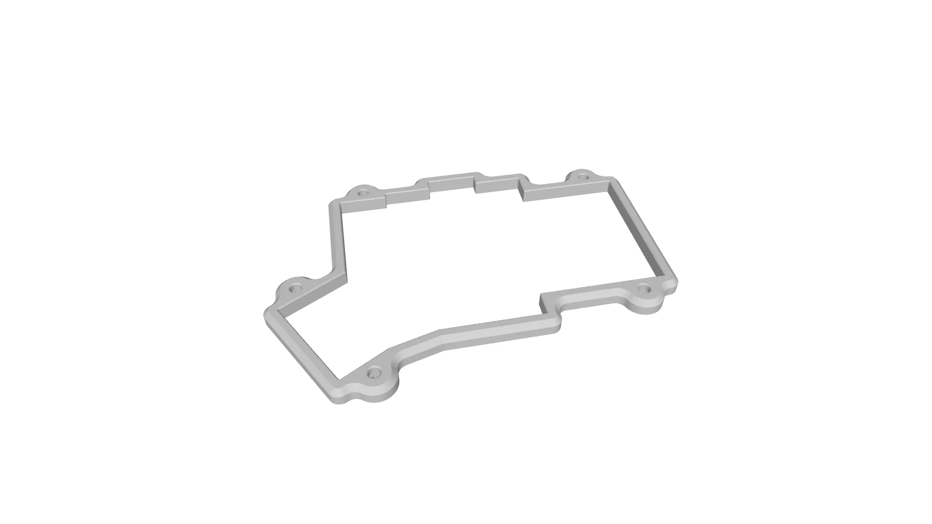 The top case sports clean lines with chamfered edges and thoughtfully placed port openings
 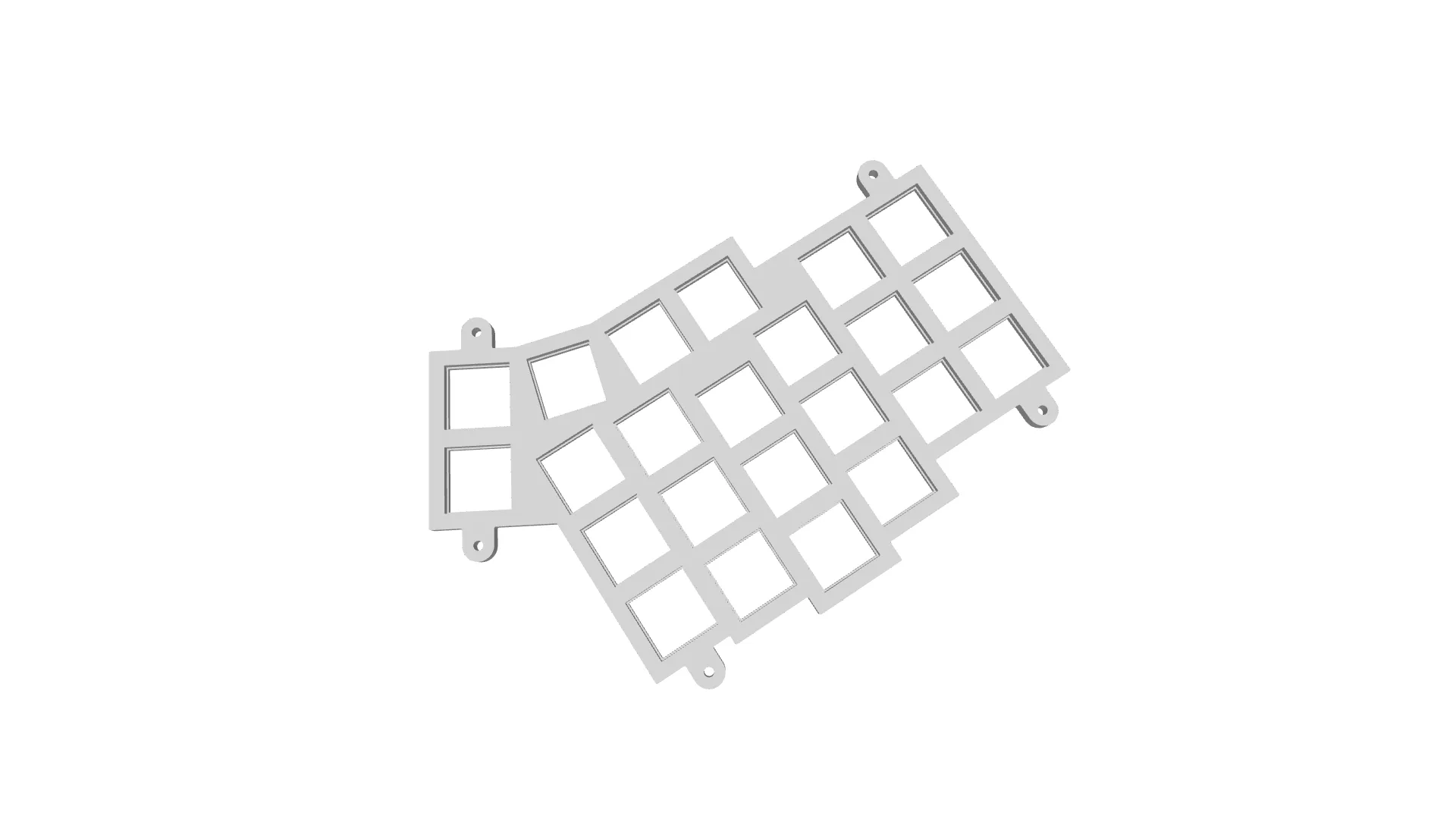 Your switches will snap into this precisely designed plate
 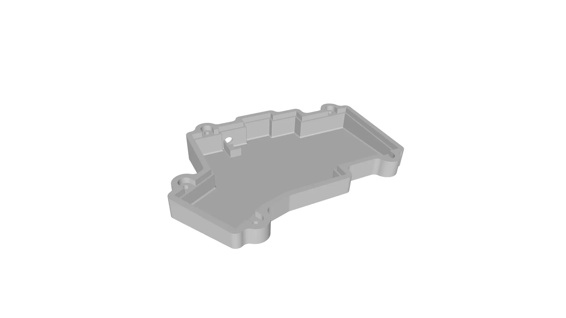 The bottom case comes ready for heat-set inserts and connection ports
Electronics
- 2× Pro Micro controllers (or compatible)
- 1N4148 diodes (one per key)
- TRS/TRRS cable (connects the halves)
- USB-C cable (connects to your computer)
- Mechanical switches (MX style)
- 2× TRRS jacks (female)
- 16 AWG wire for the matrix
Tools & Hardware
Must-haves:
- Temperature-controlled soldering iron
- 60/40 or 63/37 solder
- Wire cutters/strippers
- Needle nose pliers
- Tweezers
- 10× M2 screws and heat-set inserts
- Multimeter for testing
Nice-to-haves:
- Helping hands/PCB holder
- Desoldering pump
- Masking tape
- Isopropyl alcohol for cleanup
Bill of Materials
| Component | Quantity | Cost (INR) | Notes |
|---|---|---|---|
| 3D Printed Parts | 1 set | ₹250 | Includes top case, bottom case, and switch plate (cost with own printer) |
| Pro Micro Controllers | 2 | ₹800 | Main microcontrollers for both halves |
| Mechanical Switches | ~60 | ₹800 | MX-style switches |
| Keycaps | 1 set | ₹1,000 | Commercial keycaps |
| or | ₹100 | 3D printed alternative | |
| Copper Wire | 1 meter | ₹100 | For matrix and connections |
| Reset Switch + TRRS Jacks | 2+2 | ₹20 | For firmware flashing and half connection |
| Solder | - | ₹50 | For all connections |
| Diodes (1N4148) | ~60 | ₹50 | One per key |
| M2 Screws | 10 | ₹15 | For case assembly |
| M2 Heat-Set Inserts | 10 | ₹15 | For secure screw mounting |
| TRRS Cable | 1 | ₹150 | For connecting both halves |
| Total (with commercial keycaps) | ₹3,250 | ||
| Total (with 3D printed keycaps) | ₹2,350 |
Notes:
- Prices are in Indian Rupees (INR)
- Costs may vary based on:
- Vendor selection
- Component quality
- Bulk purchasing
- Location
- Market availability
- The 3D printing cost assumes:
- Own printer ownership
- Basic filament
- Electricity costs
- Tool costs (soldering iron, multimeter, etc.) are not included as they can be reused for other projects
- Copper wire length (1m) is sufficient for wiring both halves
- M2 screws and heat-set inserts are sold in sets, prices shown are for 10 pieces each
Let’s Build It
1. 3D Printing
Getting the Orientation Right
- The models come pre-oriented for optimal printing
- If they load differently, here’s what you want:
- Top and bottom cases: Bottom face down
- Switch plate: Top face down (smaller switch holes touching the plate)
About Those Supports
- Bottom case: You’ll want supports around the ports
- Switch plate: Skip the supports
- Top case: No supports needed
Print Settings That Work
- 0.2mm layer height
- 20% infill
- 0.4mm nozzle
2. Getting the Hardware Ready
Preparing Your Case
Let’s start with a thorough inspection of your printed parts. You’ll want to check the top, bottom, and switch plate for any printing quirks or rough spots.
Grab some sandpaper or a hobby knife to smooth out any problem areas, but don’t go overboard - we want everything to fit just right. A quick wipe with isopropyl alcohol will get rid of any dust or printing residue.
Installing Your Switches
Now comes the satisfying part - clicking in those switches. Take your time placing each one into the switch plate cutouts. Make sure they sit flush and straight - it’ll make a difference in how your keyboard feels.
Adding Those Brass Inserts
These little brass inserts will keep your keyboard firmly together. Fire up your soldering iron and carefully melt each insert into its designated spot in the bottom case. They should sit perfectly flush - no wobbling allowed. Let them cool completely before moving on.
Here’s a helpful video guide:
3. Time to Wire
Planning Your Matrix
Before we start soldering, let’s map out our key matrix. Think of it as a grid where rows and columns intersect to create each key position. 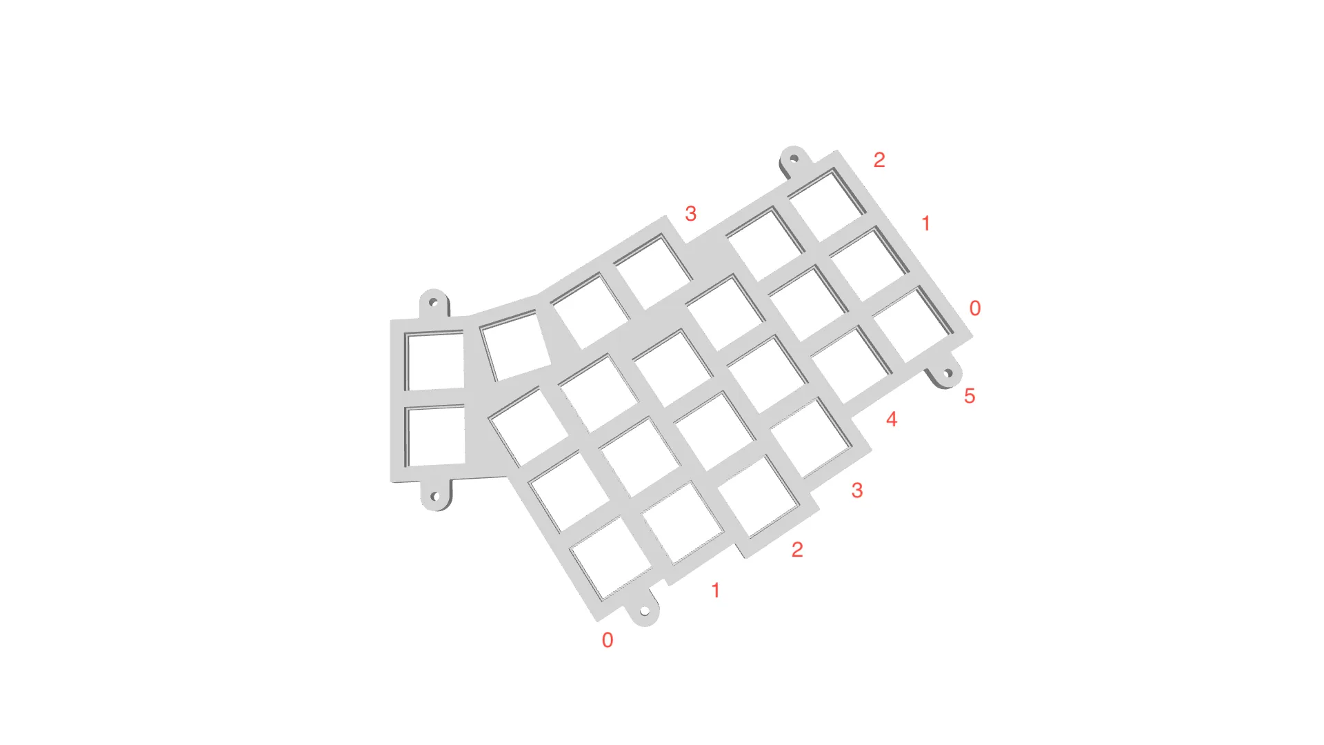 Match these intersections to where your keys will sit. For instance, your top left key might live at Row 1, Column A.
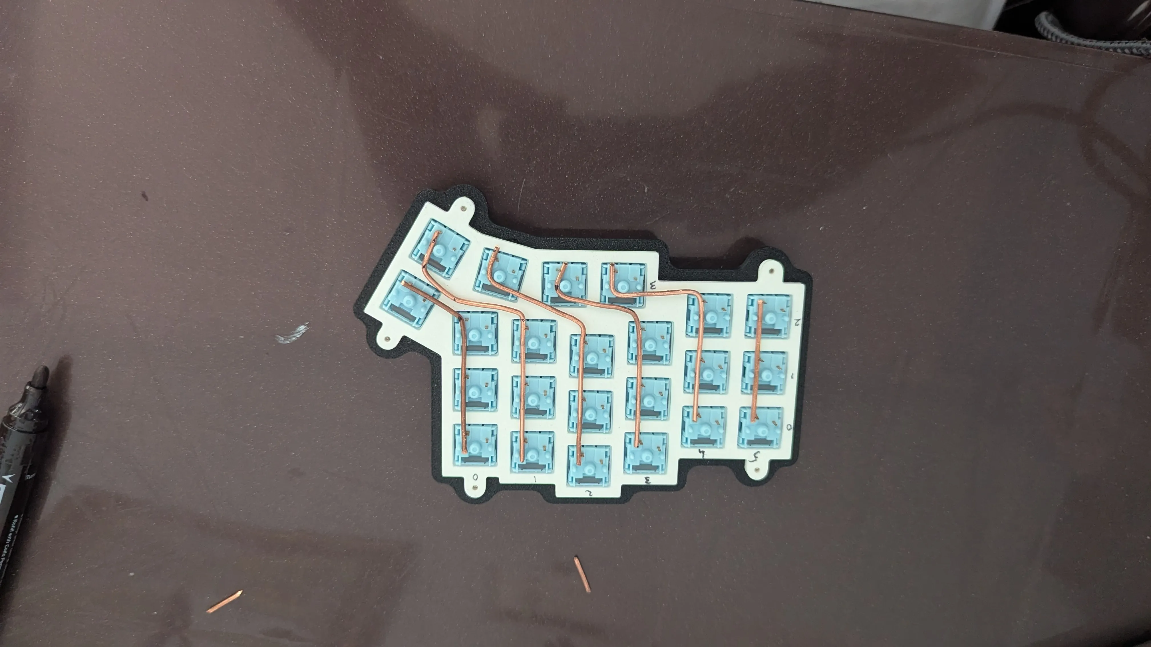
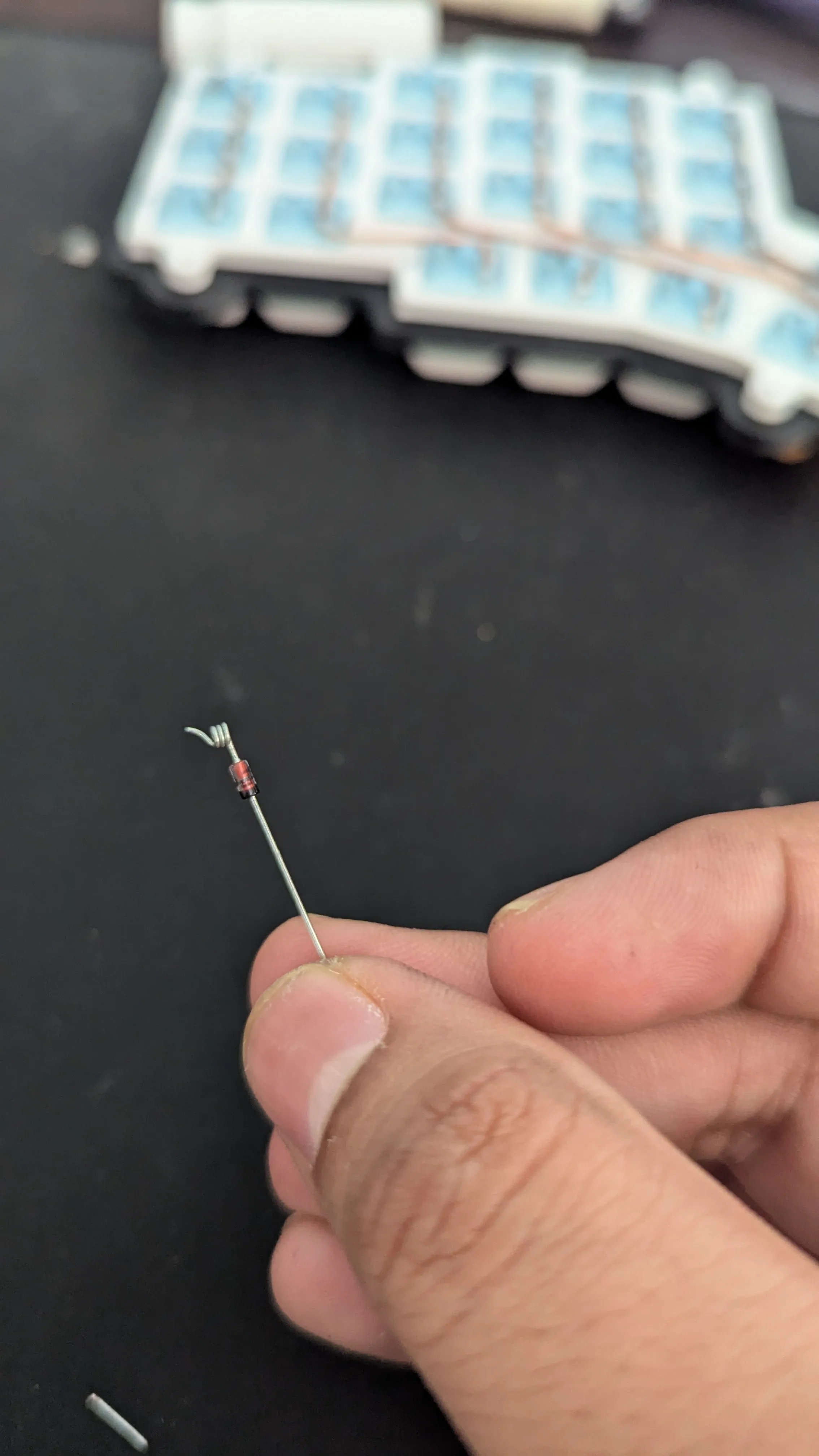
Installing Those Diodes
I discovered a fantastic tool for this step - Joe Scotto’s 3D printed diode coiling jig. It’ll help you pre-coil one leg of each diode, making them much easier to solder to your switch pins.
Check out how to use it in this YouTube clip. Want to print your own? Grab the STL files from Joe’s ScottoKeebs GitHub repository. 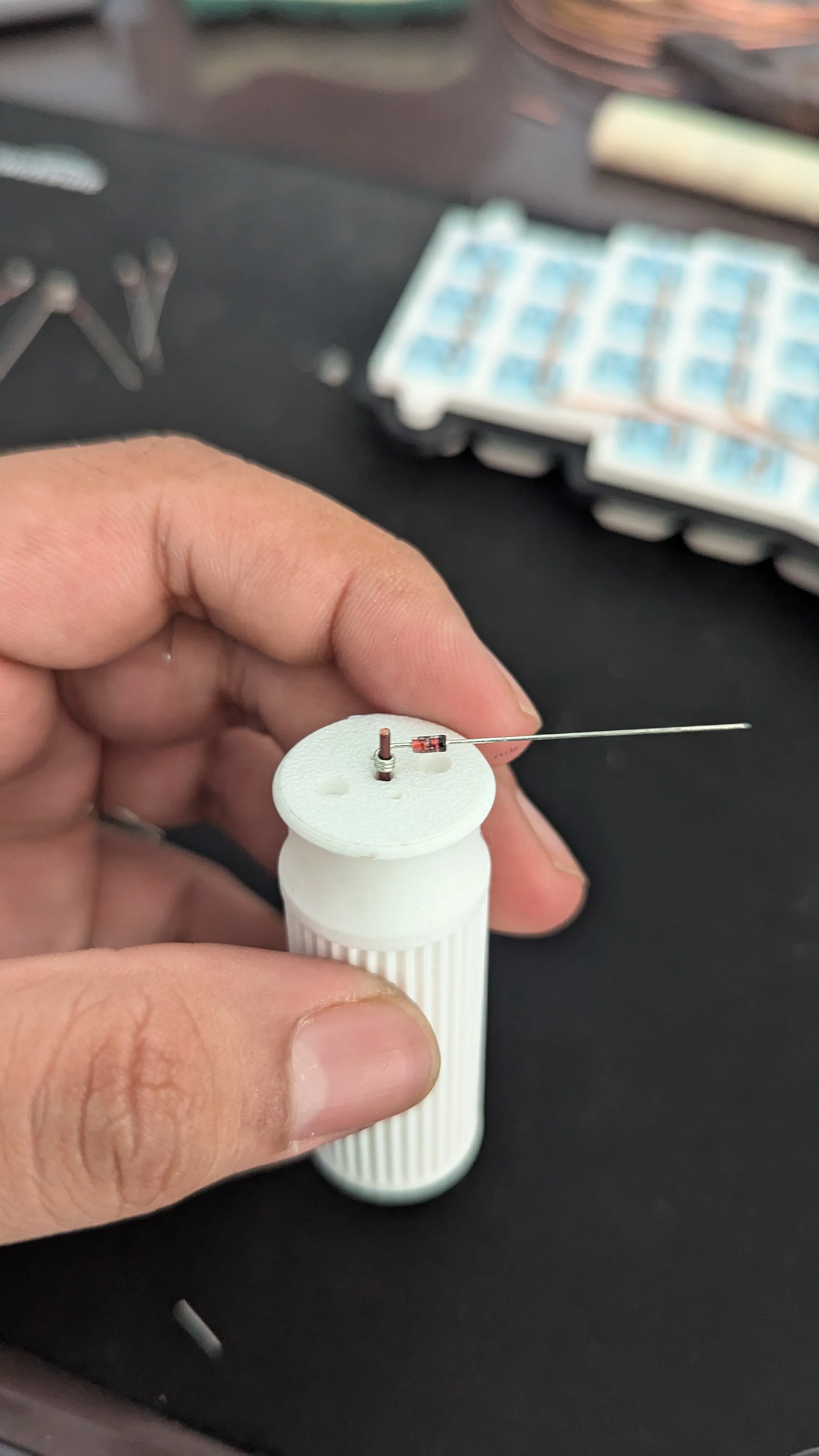
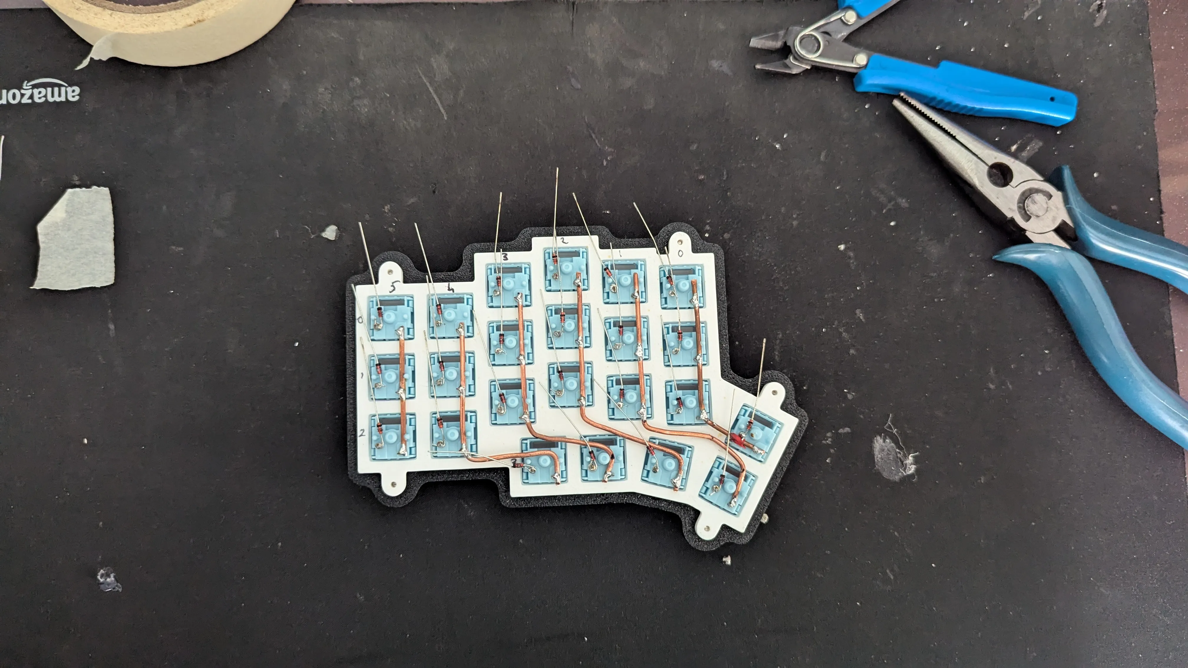
Wiring Your Rows
With your diodes in place, let’s tackle the rows. You’ll run 16AWG wire horizontally across your switches.
Wherever row wires cross column wires, slip on some heat shrink tubing to prevent shorts. Wrap each diode’s free end around its row wire to keep everything secure. Don’t forget to label your rows - it’ll save you headaches later. 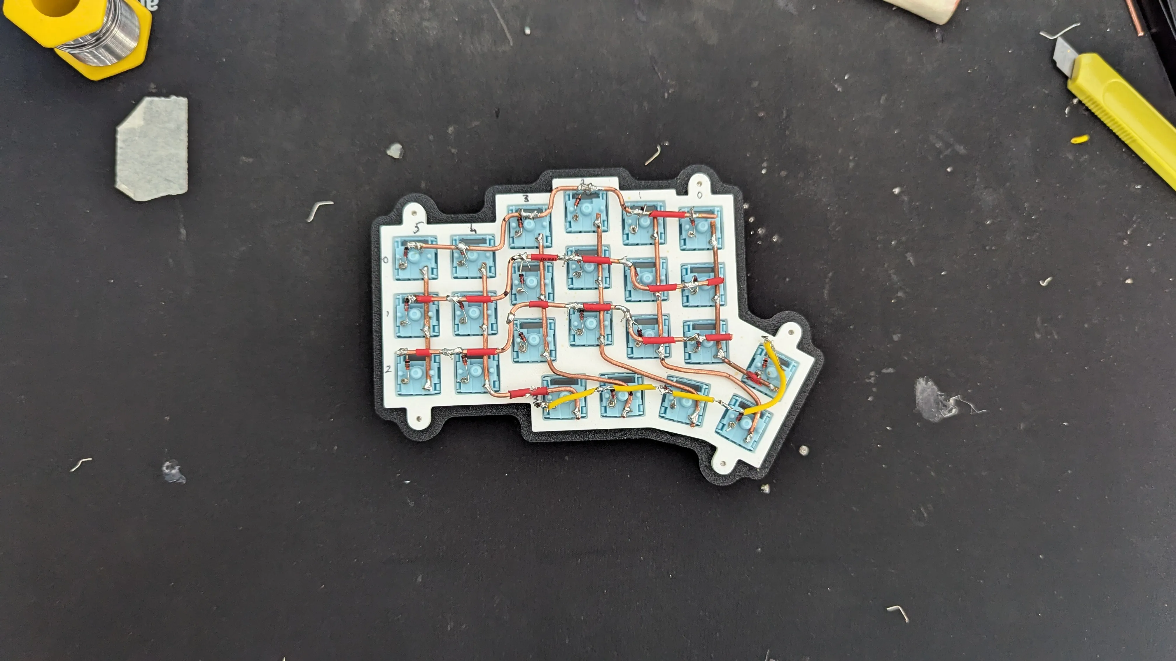
Connecting the Pro Micros
Here’s your Pro Micro pinout guide: 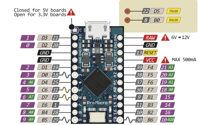
And here’s where everything goes:
ROW0 ROW1 ROW2 ROW3
B1 B3 B2 B6
COL0 COL1 COL2 COL3 COL4 COL5
D4 C6 D7 E6 B4 B5
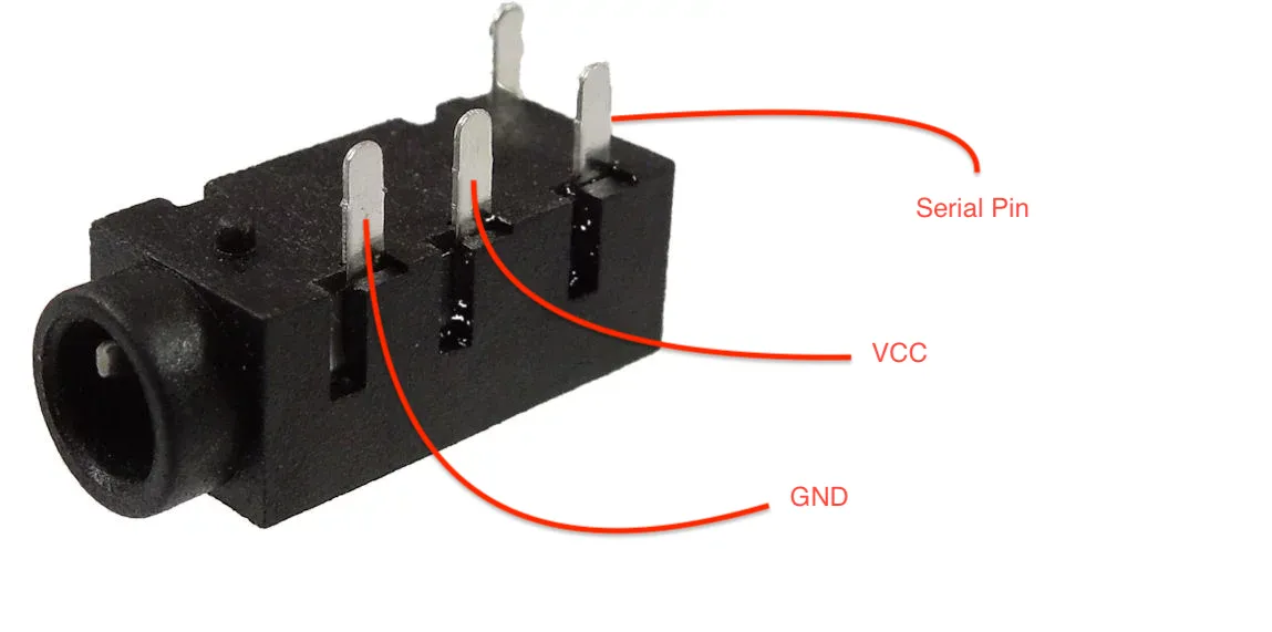
Serial Pin
D1
Now it’s time to hook up those Pro Micros - they’re the brains of your keyboard. Connect your row and column wires to the right pins, using your matrix plan as a guide. Add some heat shrink tubing to keep those connections safe and secure.
TRRS Jack Installation
You’ll need to wire up those TRRS jacks too - they’re how your keyboard halves will talk to each other.
Take your time here. Use your multimeter to check for shorts or breaks as you go. Leave some slack in your wiring - it’ll make life easier when you’re putting the case together later.
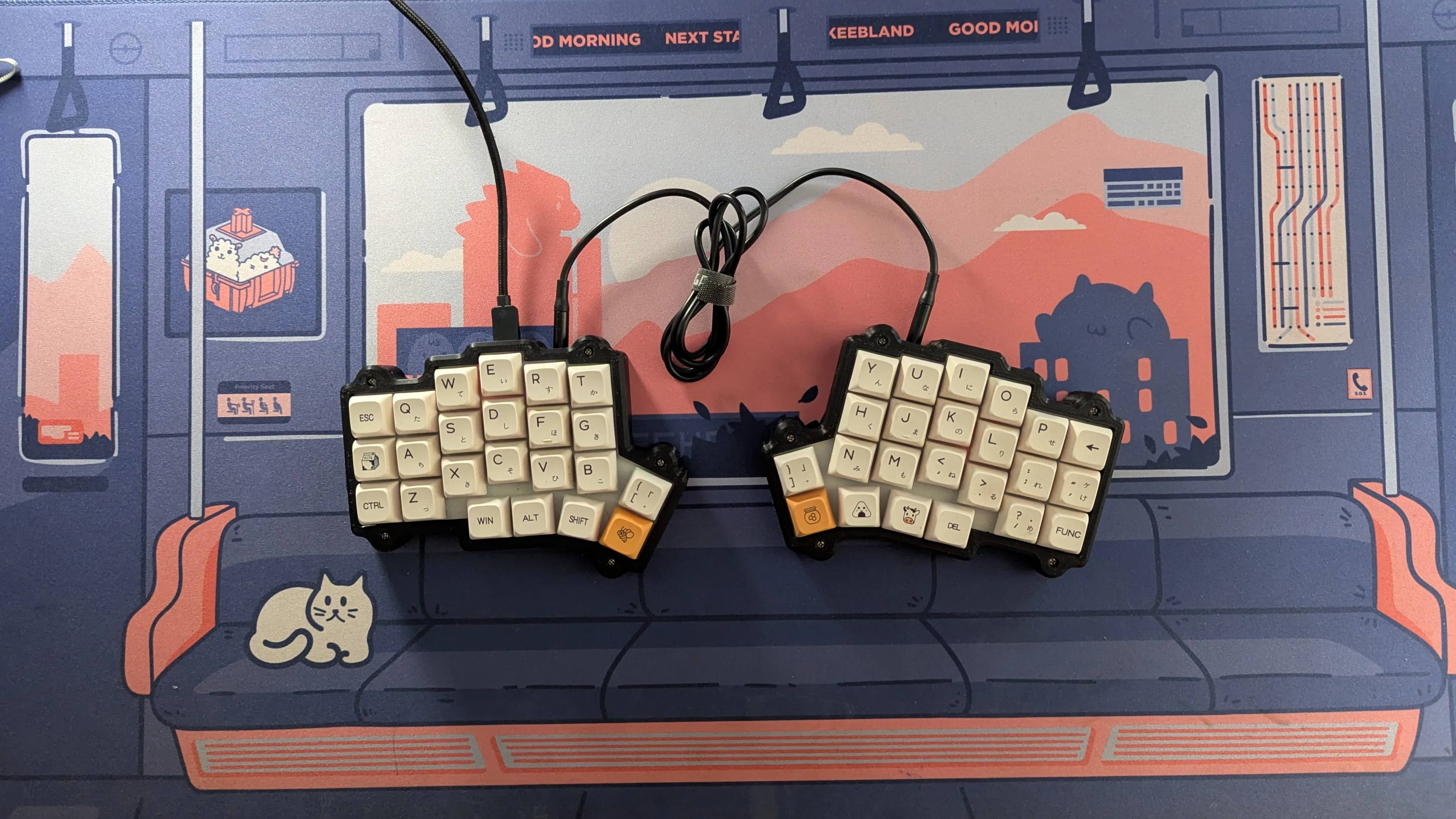
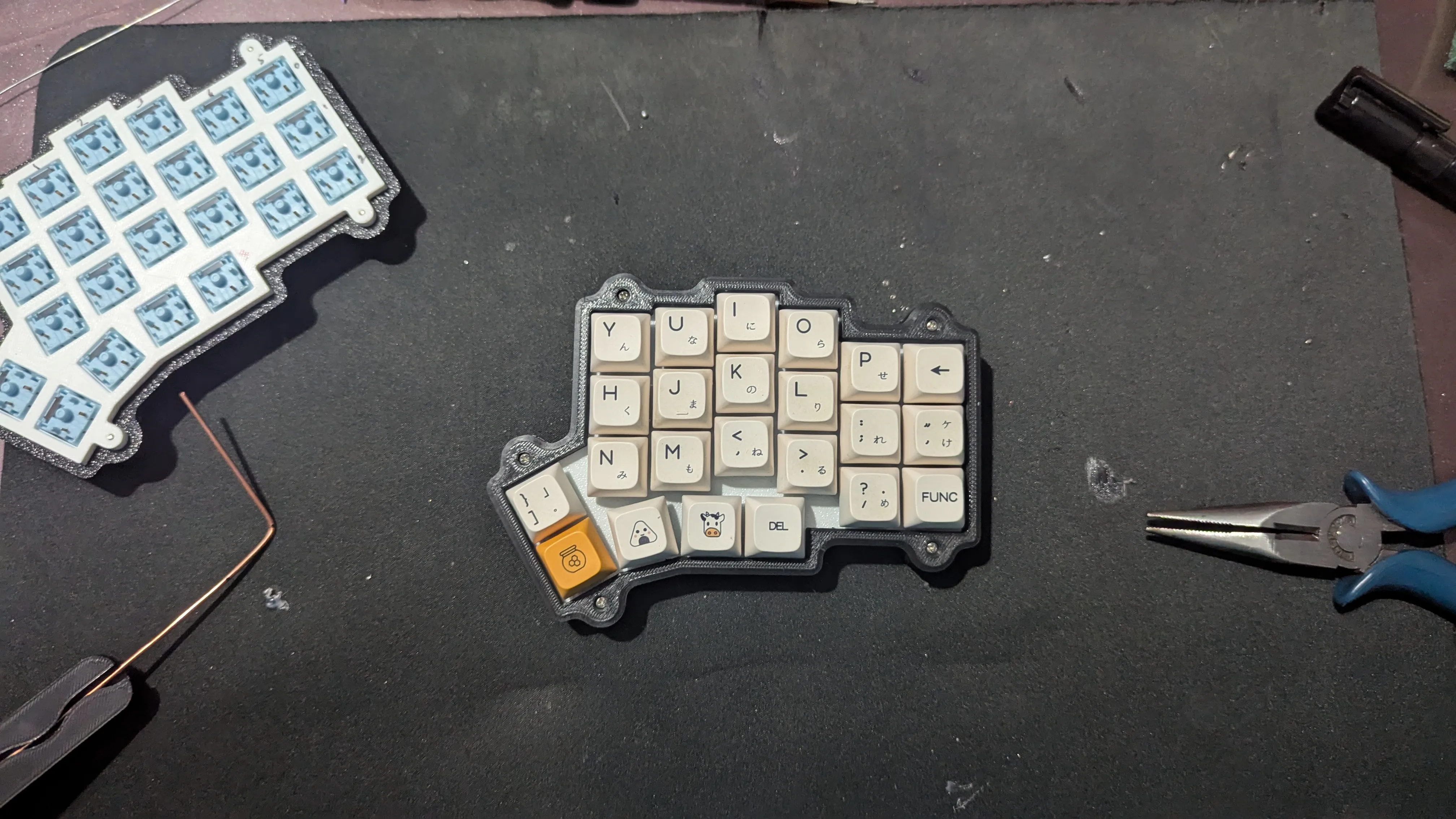 Right half looking sharp with its keycaps on
4. Bringing It to Life with Firmware
You’ll find the VOID Ergo S firmware files ready to go in the project’s GitHub repo. Grab QMK Toolbox, load up the right firmware file for your layout, and get ready to flash. Short the RST and GND pins twice to put your Pro Micro in flashing mode, then hit that “Flash” button.
Do the same for your second half, and you’re in business. 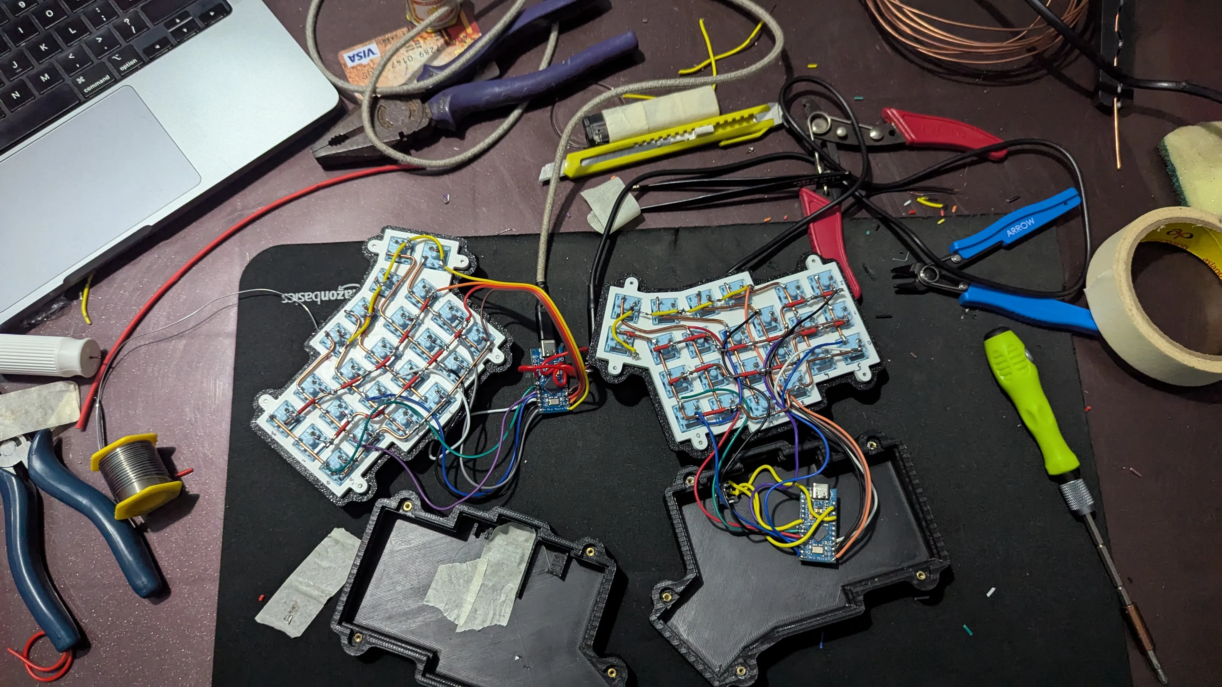 It might look messy, but that’s the real deal - no Instagram filters here!
5. Putting It All Together
Closing Up Shop
Now’s the moment of truth. Line up your case pieces carefully - you want those mounting holes to match perfectly. Use your M2 screws to connect everything through those brass inserts you installed earlier. Take your time here - rushing now could undo all your hard work.
Testing It Out
Before you get too excited about those keycaps, let’s make sure everything works. Plug in both the USB and TRRS cables, and fire up QMK Toolbox or your favorite testing tool. Press each key and make sure it registers. If something’s not right, you’ll want to track down any wonky wiring or solder joints now.
Adding Your Keycaps
Finally, the fun part! Pop on your keycaps, making sure each one’s seated properly. With that last satisfying click, your VOID Ergo S is ready to roll.
Looking Back
Building this keyboard has been quite the adventure. Starting with just some 3D printed parts and a handful of electronics, I’ve created something that’s not just functional, but truly mine. Every solder joint and wire represents a small victory, and the end result is a keyboard that’s taught me as much about electronics as it has about patience.
The VOID Ergo S has become more than just my daily driver - it’s a conversation starter and a testament to the DIY spirit. Sure, the split layout took some getting used to, but now I can’t imagine typing any other way. The tactile feedback from my chosen switches, combined with the ergonomic design, has transformed my typing experience into something that’s both comfortable and uniquely satisfying.
For anyone considering this build - yes, it’s challenging, and yes, you might question your sanity during the wiring phase. But trust me, that first time you type on a keyboard you built with your own hands? That feeling makes it all worthwhile. Whether you’re a keyboard enthusiast, a DIY lover, or just someone looking for a weekend project that’ll push your skills, the VOID Ergo S won’t disappoint.